Last UPDATED March 9 2024
4L80e - Paddle Shifters
Here is how I set up paddle shifters on my car. I have a 1987 Monte Carlo SS steering wheel on it and I adapted paddle shifters that mount to the wheel. I have the wiring set up so that it goes through the column using a pancake slip-ring. The car has a factory tilt steering column and there isn't much room for anything between the steering wheel and the internal turn signal switch. Some compromising must be done to get it to work with the wheel. Let's see how it goes.
First, I searched for a basic, but easy to be mounted paddle shifter. My searching eBay and Amazon found some that fit a late model BMW. These were relatively cheap coming in about $150.

I had to fabricate some shifter mounts to integrate into the Monte Carlo SS steering wheel. I made some that would insert into the openings on each spoke like in the picture below. I drilled a hole in each plate so the shifters could be tightened up and pinch the plate in place. In the picture below, you'll also see two momentary push buttons for either a Trans-Brake or Boost-Launch button and a Manual Boost Build button. I'm installing both of these options along with the paddle shifters.

The BMW shifters use some resistors so they can communicate properly with the stock BMW controls. The Holley ECU I'm using only needs a momentary ground to make the ECU upshift or downshift. I had to reconfigure the wiring within the shifters and bypass the resistors as shown below.
.jpg)
I also had to source what's called a "Printed Circuit Board Pancake Slip Ring Electrical Rotary Joint". The inner hole in the ring is 38.1mm in diameter and the outside diameter is 93mm. It has a 6 Way electrical circuit. I was able to find one of these on eBay. It's only 6mm thick and it has enough room to install it between the column and the steering wheel.
.jpg)
.jpg)
The photo's below show where I drilled a hole in the steering wheel between the spokes so the shifters and the momentary switch wires can pass into the rear side of the whee for a total of 8 wires...4 on each side. I also had to drill a hole at the bottom of the wheel to get a horn button wire through and attach it to the slip ring. There are 4 ground wires that had to be grounded directly to the steering wheel. All I done on this wheel is drill some holes and screwed the grounds down using a wire eye. See pictures.
.jpg)
.jpg)
The next photos shows where I had to add some clearance so the slip ring could mount flat to the wheel hub. A die grinder makes easy work out of this.
.jpg)
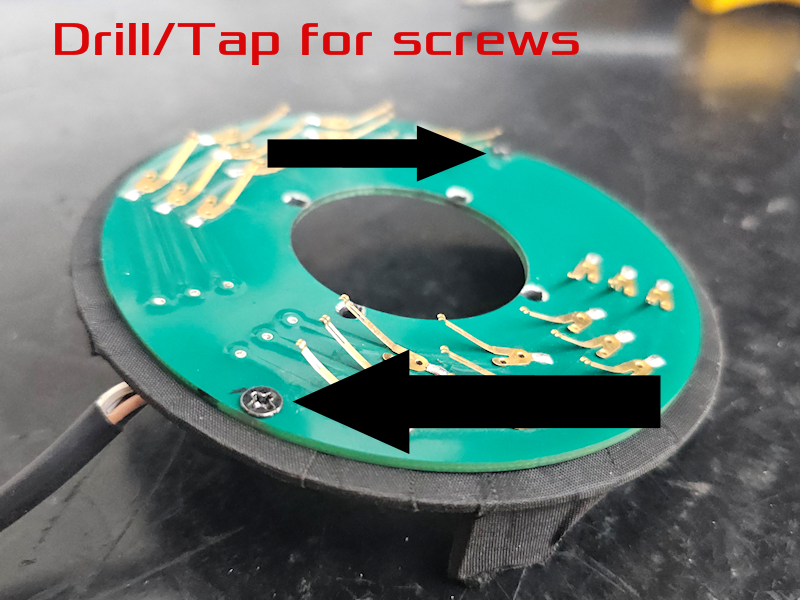
To get the ring mounted to the hub of the wheel, I placed the slip ring dead center of the hub amd marked the holes on the hub and drilled them out to 3mm. I used a thread tap to tap each hold for the screws. You can see the three tiny threaded holes in the picture below. Only three could be drilled due to the placement of a factory threaded hole. I wanted to have the wires to point at the 6 o'clock position once it's screwed in place.
.jpg)
.jpg)
The final part is to solder the wires to the slip ring and screw it to the hub. I placed some thick tape on the rear of the slip ring to protect the wires just in case.
.jpg)
In the next photo, I soldered the ground wire for the horn directly onto the horn button mount using a couple of wire terminals so I can disconnect it if I ever need to service the column in the future. The wire will go through the bottom hole I drilled and solder to the slip ring.
.jpg)
Below are pictures of the steering wheel assembled.
.jpg)
.jpg)
.jpg)
.jpg)
.jpg)
.jpg)
-------------------------------------------------------------------------------
Steering Column Slip Ring Mount - Fabrication and Assembly
The picture below shows how well the column side slip ring measures up on the OEM column. I have to fabricate a mount to get this installed over the turn signal switch.

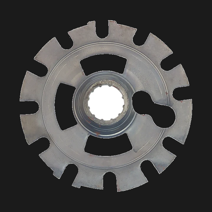
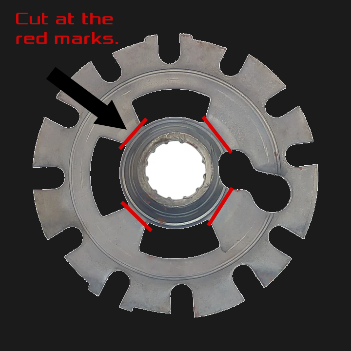
Once you remove the steering wheel, you'll have to remove the wheel locking plate. The plate will have to be cut down so it will fit through the slip ring. I cut mine down just enough so that it centers the slip ring perfectly on the column. It will then line up with the slip ring on the steering wheel when it's installed. Unfortunately, your steering wheel will no longer be able to lock when you turn the ignition key off.

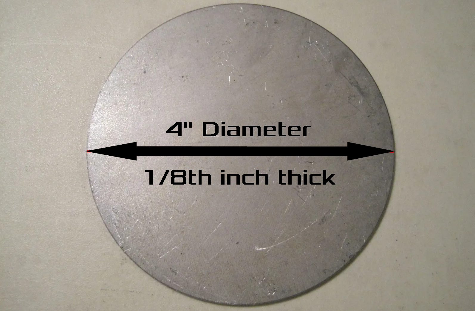
The parts needed to do a mount is a 4" x 1/8th inch round plate. You can buy one of these on eBay for less than $10. I had to cut a 2 1/4" hole in the middle of the plate to fit it over the steering shaft and to attach the slip ring.
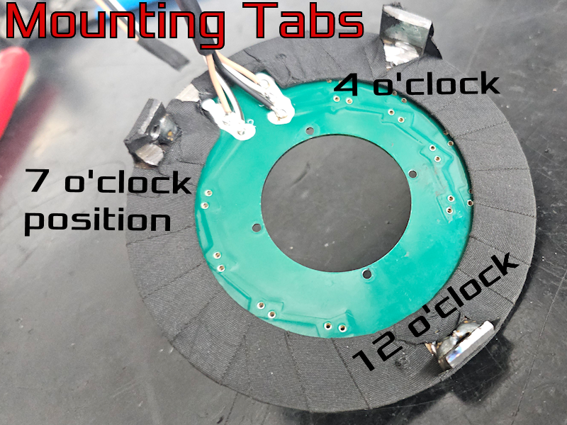
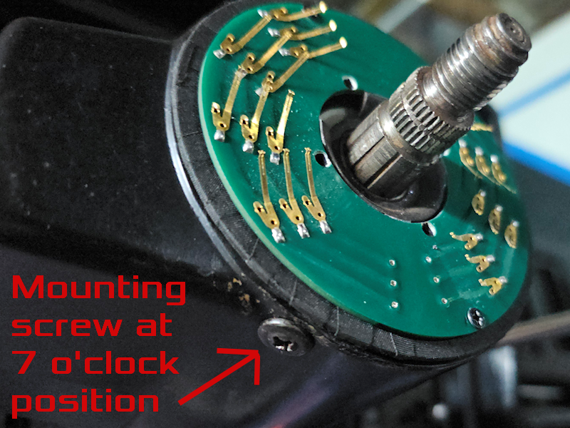
I welded on three small mounting legs at the 12 o/clock, the 4 o'clock and the 7 o'clock positions so it can be mounted on the column.
 At this time, I only drilled and tapped the leg at the 7 o'clock position and screwed it to the column. You will never see the screw from above. One screw holds it in the column very good.
Once I got the column mount fabricated, I lined up the slip ring on the small lock plate and drilled and tapped two holes to attach it to the fabricated mount.
Once I got everything lined up and fitted, it was time to solder the harness to the slip ring and install it into the column.

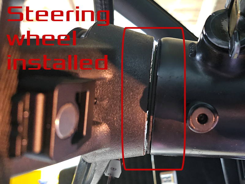
Here's the fit and finished project.

Basic video of what I done. Not all steps are included. People with fabrication skills should be able to replicate this rather easily. This set-up is using a Holley Dominator ECU that can control paddle shifting on the GM 4L80e transmission.